Frequency Meter Wiring Diagram

Vt Commodore Ignition Wiring Diagram, Complete Wiring Diagrams For Holden Commodore VT, VX, VY, VZ, VE, VF, 5.36 MB, 03:54, 32,796, John Amahle, 2018-08-01T19:37:41.000000Z, 19, Vt Commodore Ignition Wiring Diagram, to-ja-to-ty-to-my-to-nasz-swiat.blogspot.com, 1272 x 1800, jpeg, bcm pcm 12j swiat nasz, 20, vt-commodore-ignition-wiring-diagram, Anime Arts
Before installing your meter, please read this entirely and see the included wiring diagram. Instead it is sensed via the shunt at 9 and 10 (notice that 10 is closest to battery). If you have any question about the legitimacy of your wiring, feel. Shunt load (+) battery or (+) power supply wiring to all meters should be 14 or 16 awg (except sense leads on current transformer for ac ammeters).
Input power for the flow meters must be provided separately. 3s wiring diagram 1 ph, 2 wire (1 pt, 1 ct) glems would like to thank and acknowledge the use of the following meter connection diagrams from dr. Be aware that these are general diagrams using standard test switches which may not match some utility standards in their configuration and are for reference only. Input power for the flow meters must be provided separately. The block diagram of digital frequency meter is shown in figure (2). The unknown frequency signal is applied to the amplifier, where the signal is strengthened or amplified to a suitable level, and then applied to input of schmitt trigger circuit. The function of the schmitt trigger is to change the amplified input signal into square wave signal with fast rise and fall times. The basic block diagram of basic digital frequency meter (dfm) is shown in above figure. Schematic circuit diagram of the electronic frequency meter.
How to Wire A Frequency Meter (Hz-Hertz)? - Electricalonline4u

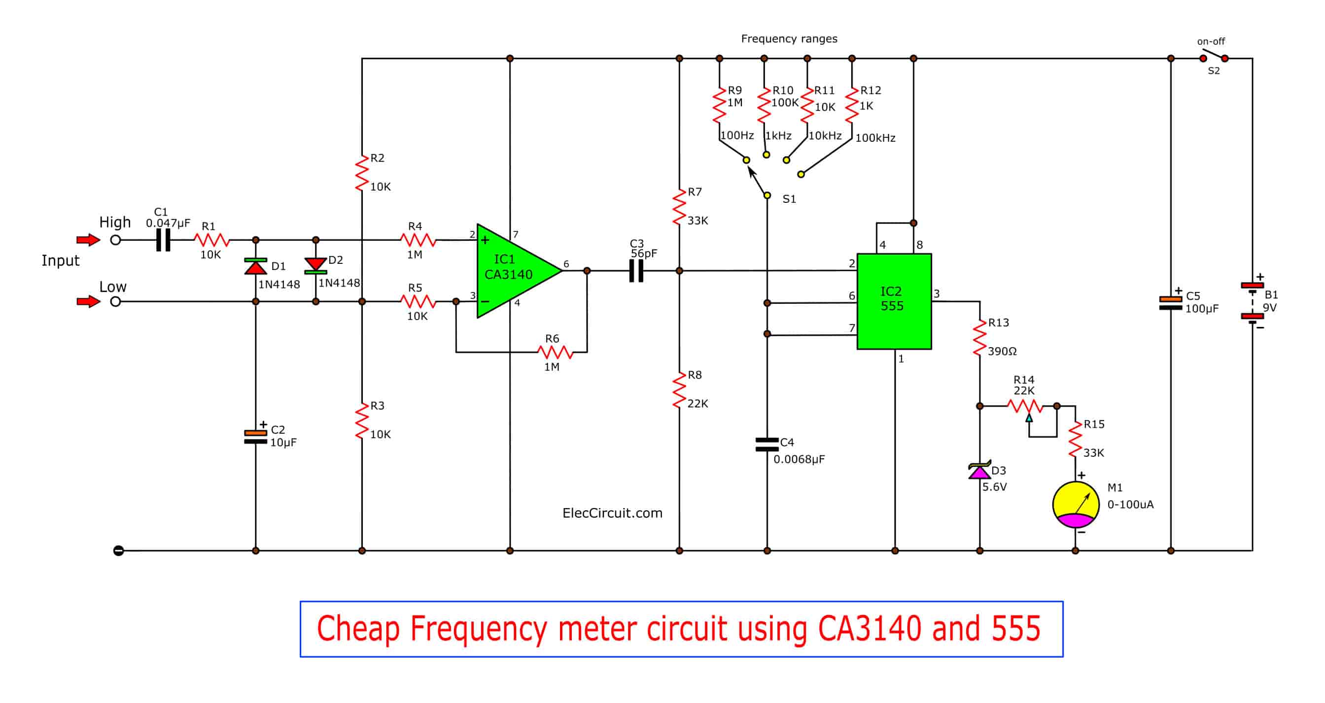
Cheap frequency meter circuit using 555 and CA3140 | ElecCircuit.com

Frequency Meter Circuit | Wiring Diagram

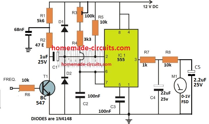
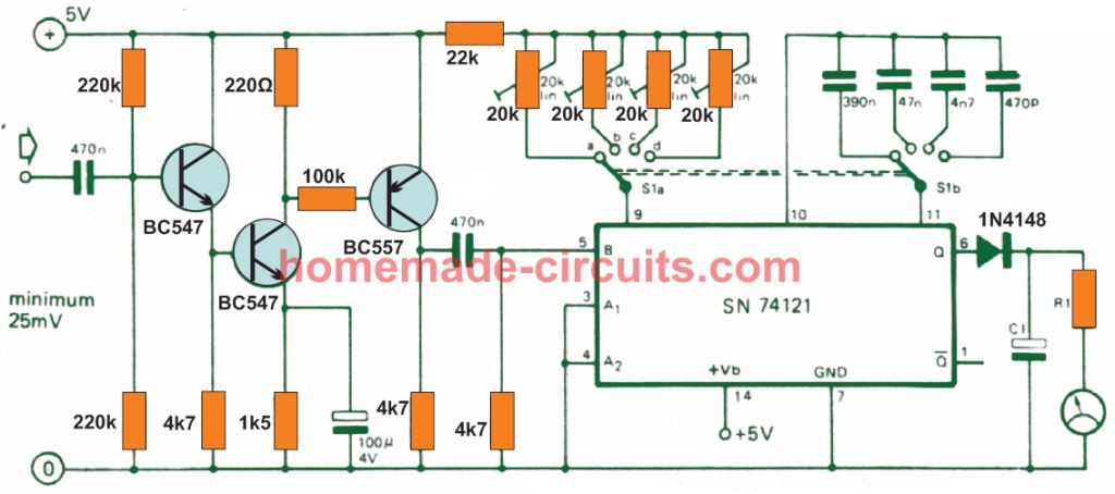
Simple Frequency Meter Circuits - Analogue Designs | Homemade Circuit Projects

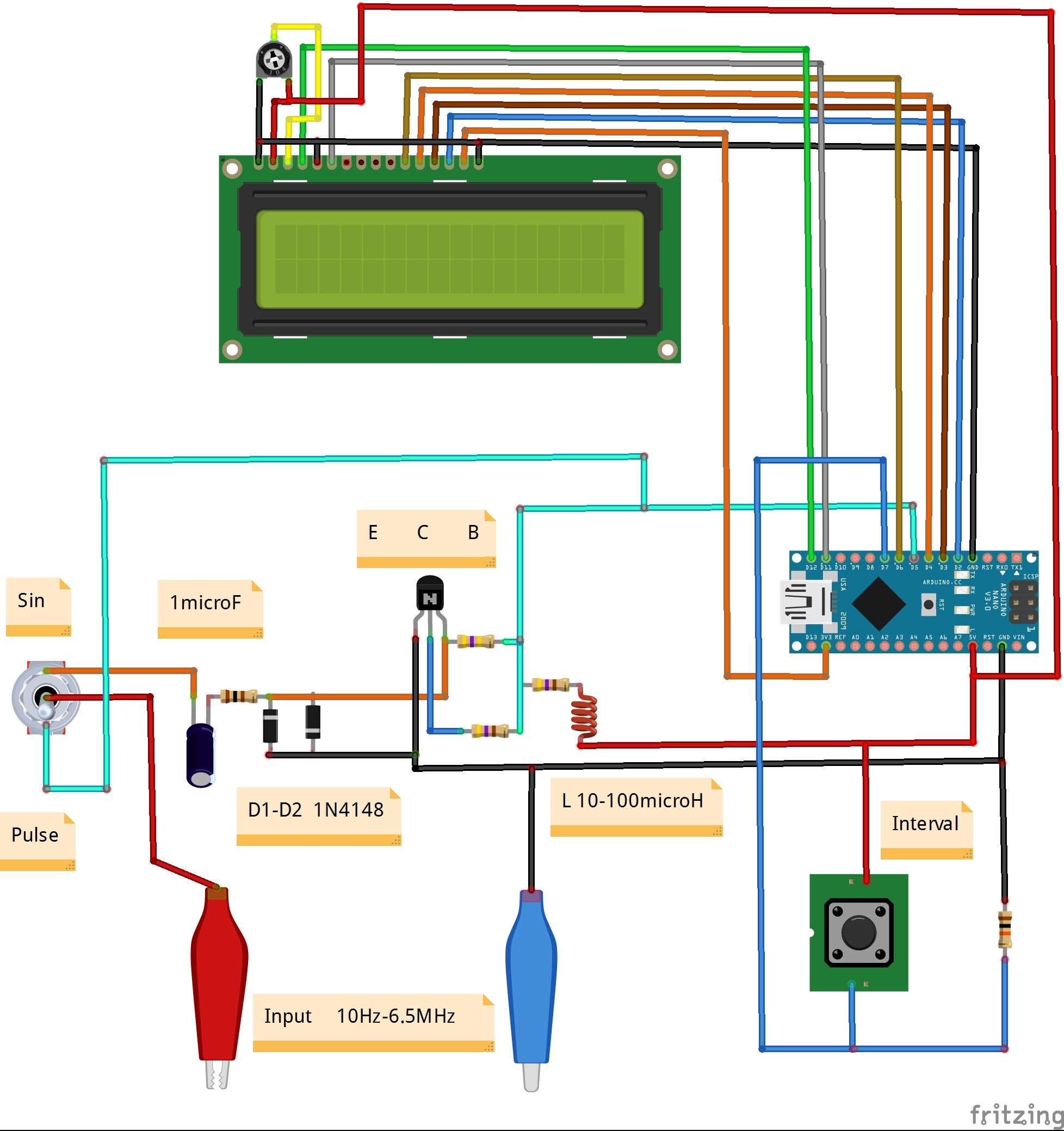
DIY Simple Frequency Meter Up to 6.5MHz - Hackster.io

Digital Frequency Meter Circuit Diagram and Working Principle | Electrical Academia

Digital Frequency Meter Circuit Diagram and Working Principle | Electrical Academia
Simple Frequency Meter Circuits - Analogue Designs | Homemade Circuit Projects

Digital Frequency Meter : Construction, Working and Its Applications

Mains line frequency meter Circuits | Electronics Peojects
