Garmin Gsd 20 Wiring Diagram

Vt Commodore Ignition Wiring Diagram, Complete Wiring Diagrams For Holden Commodore VT, VX, VY, VZ, VE, VF, 5.36 MB, 03:54, 32,796, John Amahle, 2018-08-01T19:37:41.000000Z, 19, Vt Commodore Ignition Wiring Diagram, to-ja-to-ty-to-my-to-nasz-swiat.blogspot.com, 1272 x 1800, jpeg, bcm pcm 12j swiat nasz, 20, vt-commodore-ignition-wiring-diagram, Anime Arts
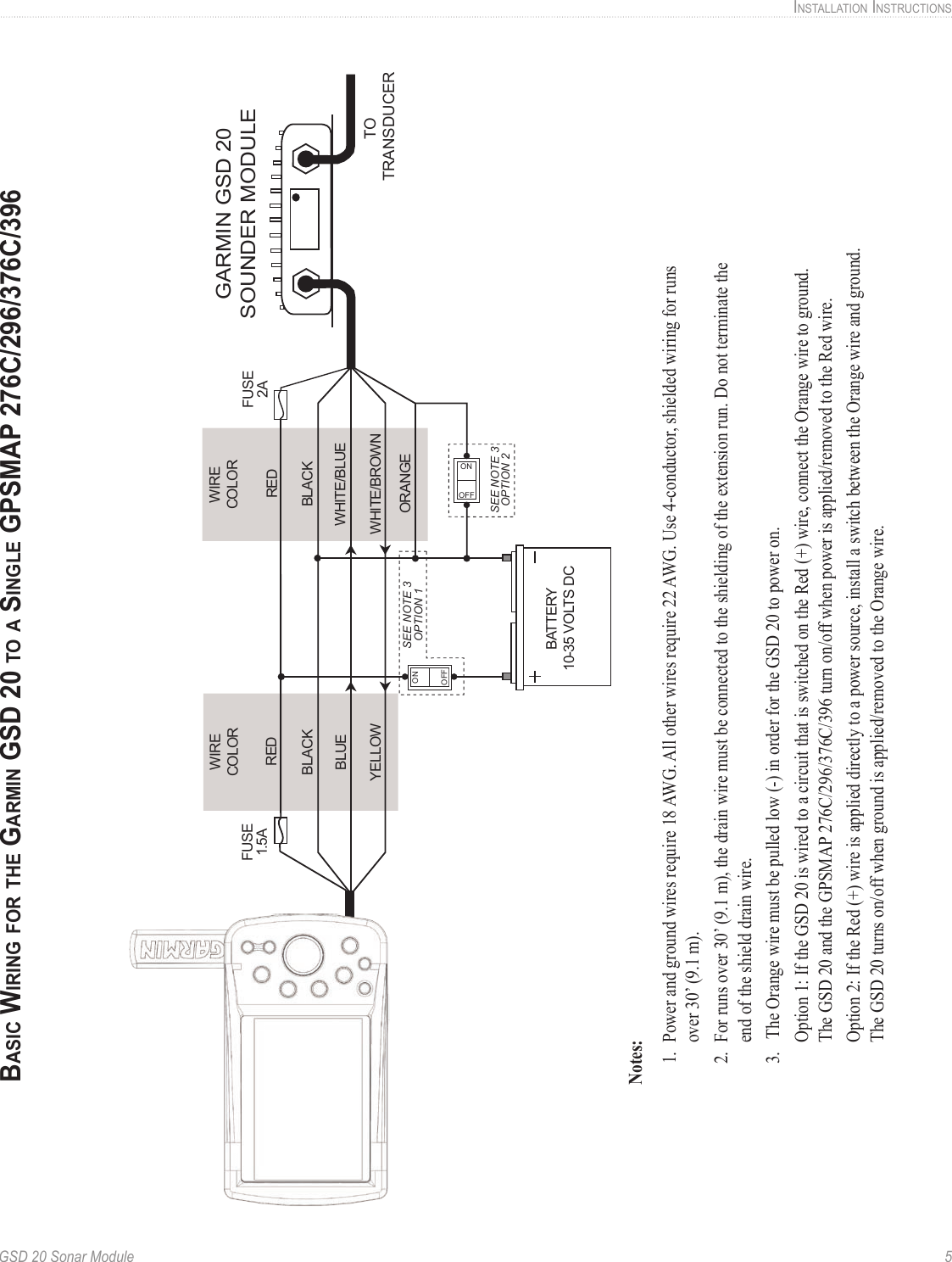
Gsd 26 installation instructions 3. Www. garmin. com \376\377mounting the sounder, page\2402 \376\377installing locking rings on the cables, page\2406 \376\377page\2406. Before you connect the wires, consult the wiring diagrams (transducer. Gsd 24 compatible transducers wiring diagram.
If you are needing to connect a transducer to a gsd 26, see related content below. Once the gsd 20 module has been installed, connect the power/data and transducer cables to the appropriate receptacle. Refer to the following wiring diagrams for connecting the gsd 20 to compatible garmin units. You can extend the wiring of the gsd 20 power/data cable up to 100’ (30 m) total length. Refer to the following wiring diagrams for connecting the gsd 20 to compatible garmin units. You can extend the wiring of the gsd 20 power/data cable up to 100’ (30 m) total length. Transducer cable extensions are available through your garmin dealer. Garmin gsd 20 wiring diagram. 21 posts related to garmin gsd 20 wiring diagram.
Garmin Gsd 20 Wiring Diagram

Garmin Gsd 20 Wiring Diagram
Garmin GSD 20 | Installation Guide - Page 8

Garmin GSD 20 | Installation Guide - Page 5

Garmin Gsd 20 Wiring Diagram
Iring, Armin - wiring | Garmin GSD 20 | Installation Guide (Page 6)

Dajte sve od sebe primijeniti željezo garmin gsd 20 wiring diagram - thegeorgiahomeconnection.com
Garmin 2010 Wiring Diagram - Style Guru: Fashion, Glitz, Glamour, Style unplugged

Wiring Manual PDF: 18 5 Wiring Diagram Garmin
