0e-1gangchim Wiring Diagram
6) panic function when the operator needs to send an alarm signal without being seen to do so, he can activate the panic function. The power supply is shown at the top and the earth at the.

Honeywell HE360 not workingconnected to Goodman GMV95/GCv9 Community Forums
If any of the original wire, as supplied, must be replaced, use the same or equivalent type wire.

0e-1gangchim wiring diagram. Also, if any information shown in this diagram differs from what the documentation for automation system shows, assume the automation documents are correct. Diagram corresponds in position to the actual wiring in these supplemental diagrams simplify the circuit trac the vehicle. Terminal markings and internal wiring diagrams single phase and polyphase motors meeting nema standards see fig.
It shows how the electrical wires are interconnected and can also show where fixtures and components may be connected to the system. They can be used as a guide when wiring the controller. The wiring diagrams are grouped into individual sections.
They show the relative location of the components. Plus, you can use it wherever you are—smartdraw runs on any device with an internet connection. That saves a lot of time because you don’t.
The main wiring diagrams are laid out so that the after the main diagrams are systems diagrams. Wiring diagram book a1 15 b1 b2 16 18 b3 a2 b1 b3 15 supply voltage 16 18 l m h 2 levels b2 l1 f u 1 460 v f u 2 l2 l3 gnd h1 h3 h2 h4 f u 3 x1a f u 4 f u 5 x2a r power on optional x1 x2115 v 230 v h1 h3 h2 h4 optional connection electrostatically shielded transformer f u 6 off on m l1 l2 1 2 stop ol m start 3 start start fiber optic. Premium color wiring diagrams get premium wiring diagrams that are available for your vehicle that are accessible online right now, purchase full set of complete wiring diagrams so you can have full online access to everything you need including premium wiring diagrams, fuse and component locations, repair information, factory recall information and even tsb's (technical.
Connect the wiring as in fig. The diagram is surrounded by a alpha/numeric loaction grid. The wiring between the 4232cbm and the vista panel will remain the same.
Therefore, the headlight circuitry is located ing for the technician. A diagram that represents the elements of a system using abstract, graphic drawings or realistic pictures. Again, the colors shown for rs422 are for illustrative purposes only.
If you cannot locate the wiring diagram on your appliance, you can call the ge appliances answer center to obtain one. A wiring diagram is a simple visual representation of the physical connections and physical layout of an electrical system or circuit. Smartdraw's wiring diagram software gets you started quickly and finished fast.
Eautorepair.net redraws factory wiring diagrams in color and includes the component, splice and ground locations right in their diagrams. All the wires at the connectors have alpha/numeric addresses showing where the other end of the wire is located ac cording to the grid. 0e start of programming 12345 e supercode 1e identification 0e bistable mode, (on/off) 55127 e new code after this operation the code 55127 will activate the relay 1 in bistable mode (on/off).
You will need to have your complete model number. If you run into an electrical problem with your gmc, you may want to take a moment and check a few things out for yourself. Electrician circuit drawings and wiring diagrams youth explore trades skills 3 pictorial diagram:
To be wired in accordance with n.e.c. If connected to multiple inputs, two of the respective tones will sound in the following order: These codes set in the sensing and diagnostic module (sdm).
Begin with the exact wiring diagram template you need for your house or office—not just a blank screen. Field power wiring ground see rating plate for volts & hertz disconnect per nec see note. B0012 0e, b0013 0e, b0016 0e, b0019 0e, b0020 0e, b0022, b0023 0e, b0033 0e, b0040 0e, or b0042.
Use copper wire (75ºc min) only between disconnect switch and unit. Wiring diagrams description these diagrams use a new format. A single trigger may be connected to one or more of the three trigger inputs, depending on the type of tone desired.
A diagram that uses lines to represent the wires and symbols to represent components. + other fans as shown brown black blue m 1~ green/y ellow brown cap black ce31 only single phase ac motor with capacitor blue or grey a n sildes these diagrams mainly apply to external rotor motorsbut some standard.
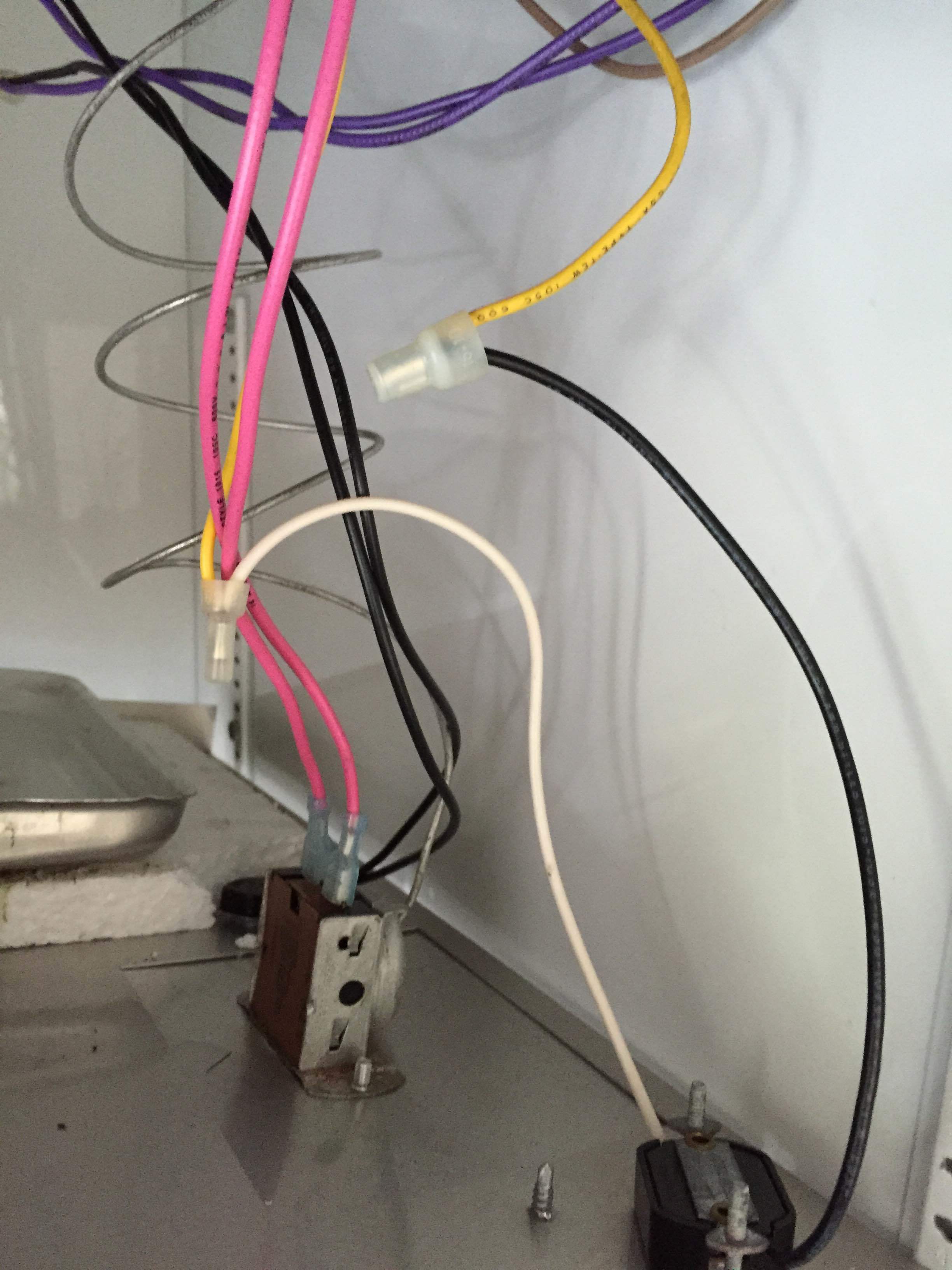
Any HVAC gurus on here? Looking for help with wiring a thermostat The Hull Truth Boating and

I HAVE 3 FUEL HOSES ON MY CRAFTSMAN CHAINSAW WITCH ONE GOES DIY Forums
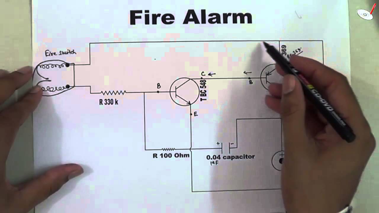
How does a Fire Alarm Electronic Circuit Works by Raj Kumar Thenua YouTube
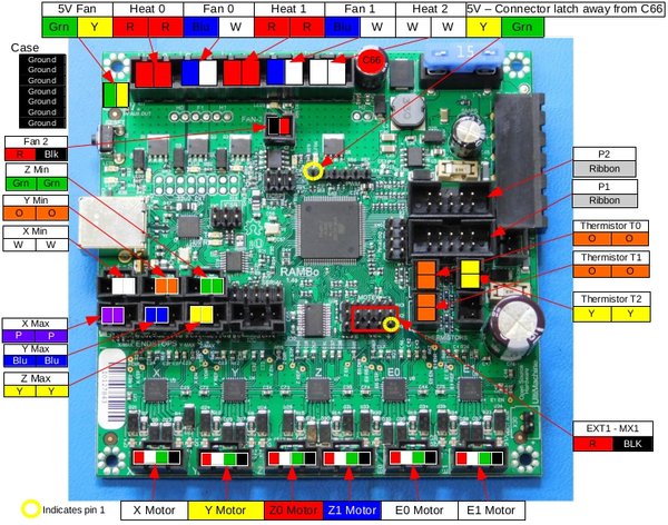
True GDM26 SSR Wiring with full compressor take over Hardware BrewPi Community

wiring diagram needs for 01 rubicon 500 Honda Foreman Forums Rubicon, Rincon, Rancher and
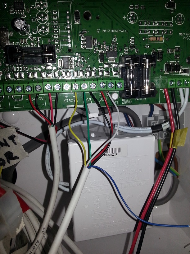
Honeywell Accenta G4 Wiring To New Siren. !!..DIY Installers..!! Security Installer Community
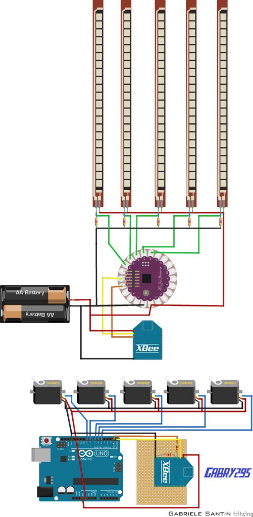
Arduino Blog » Wireless Controlled Robotic Hand made with Arduino Lilypad

Wiring help needed for a 1phase 220v reversing puzzle South Bend Mill

Weil McLain CGa gas fired boiler wont fire Community Forums
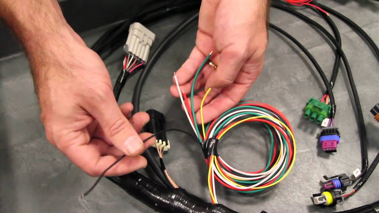
Holley EFI Tech Main Harness Overview YouTube
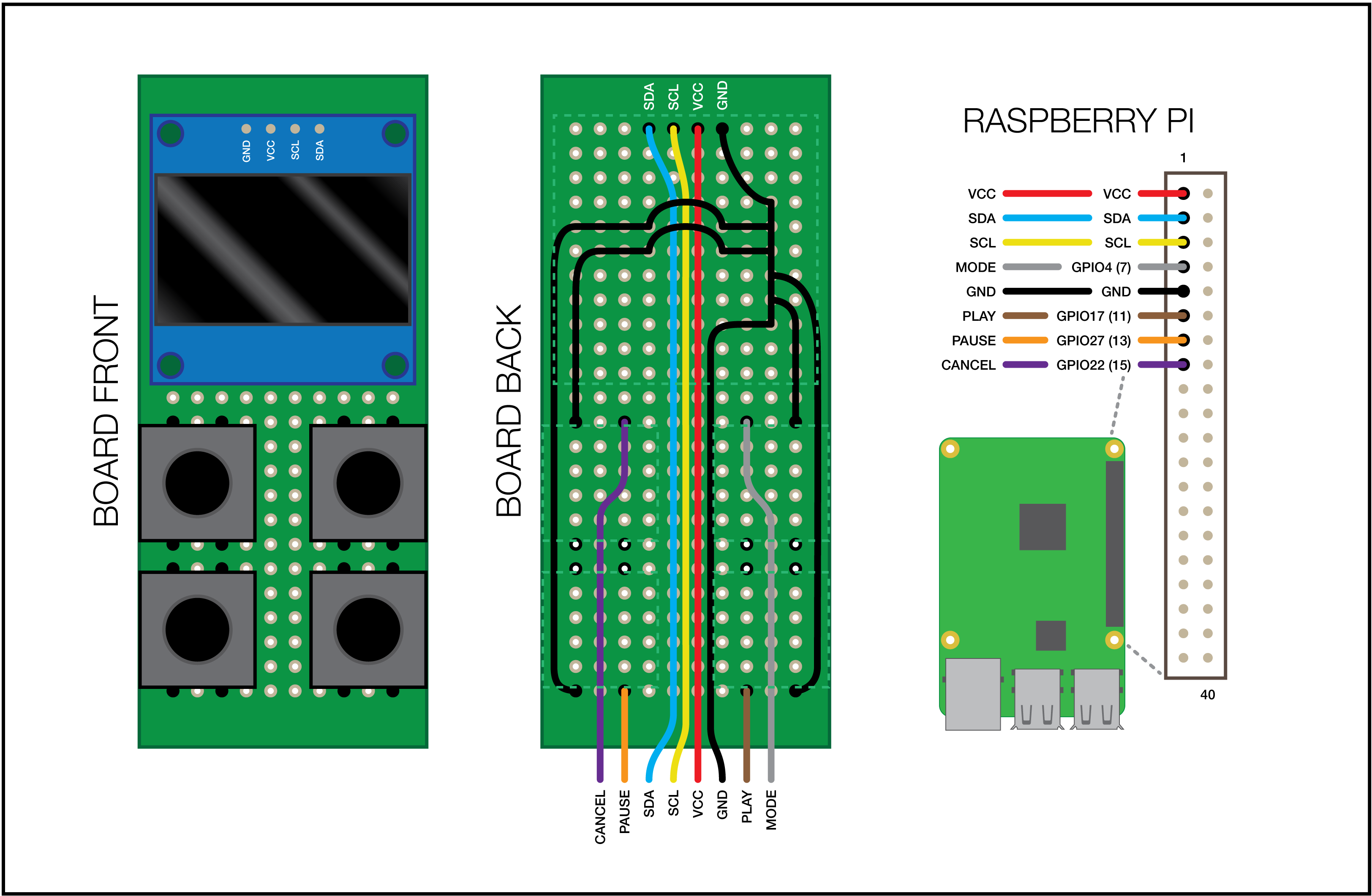
OctoPrint Micro Panel

cdi wiring help please cb400t

Bridgeport Series 1 refit need help!
OHAI Open Hardware Assembly Instructions
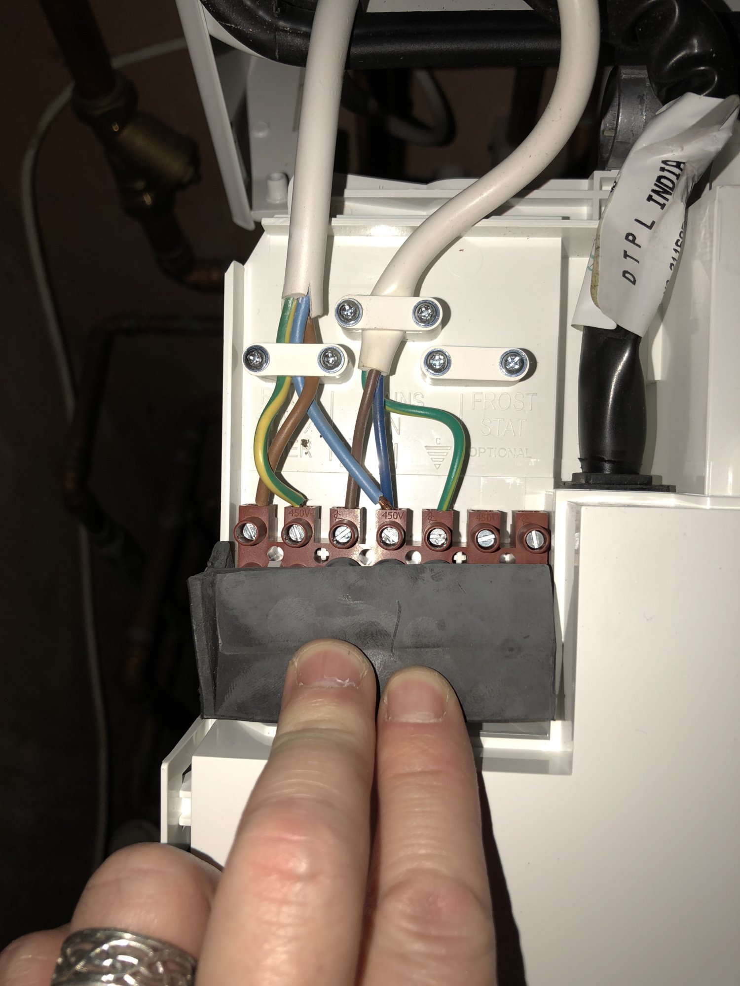
Hive and Potterton Titanium DIYnot Forums
Help with logic 30 Combi and hive wiring please DIYnot Forums
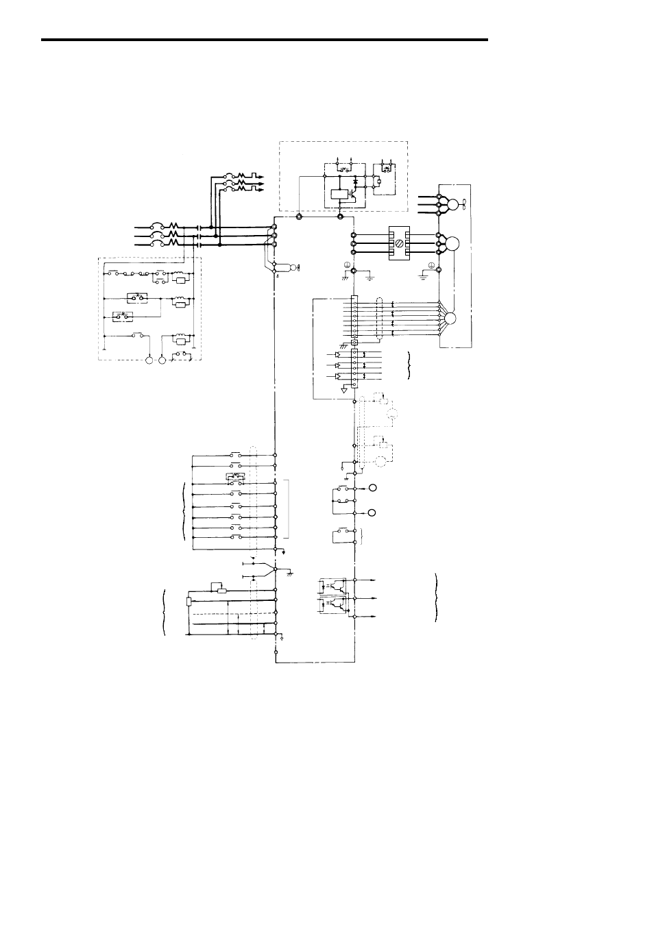
2 connection diagram, Fig. 7 connection diagram Yaskawa Varispeed686SS5 CIMRSSA User Manual
Miller CP200 converted to 240v single phase
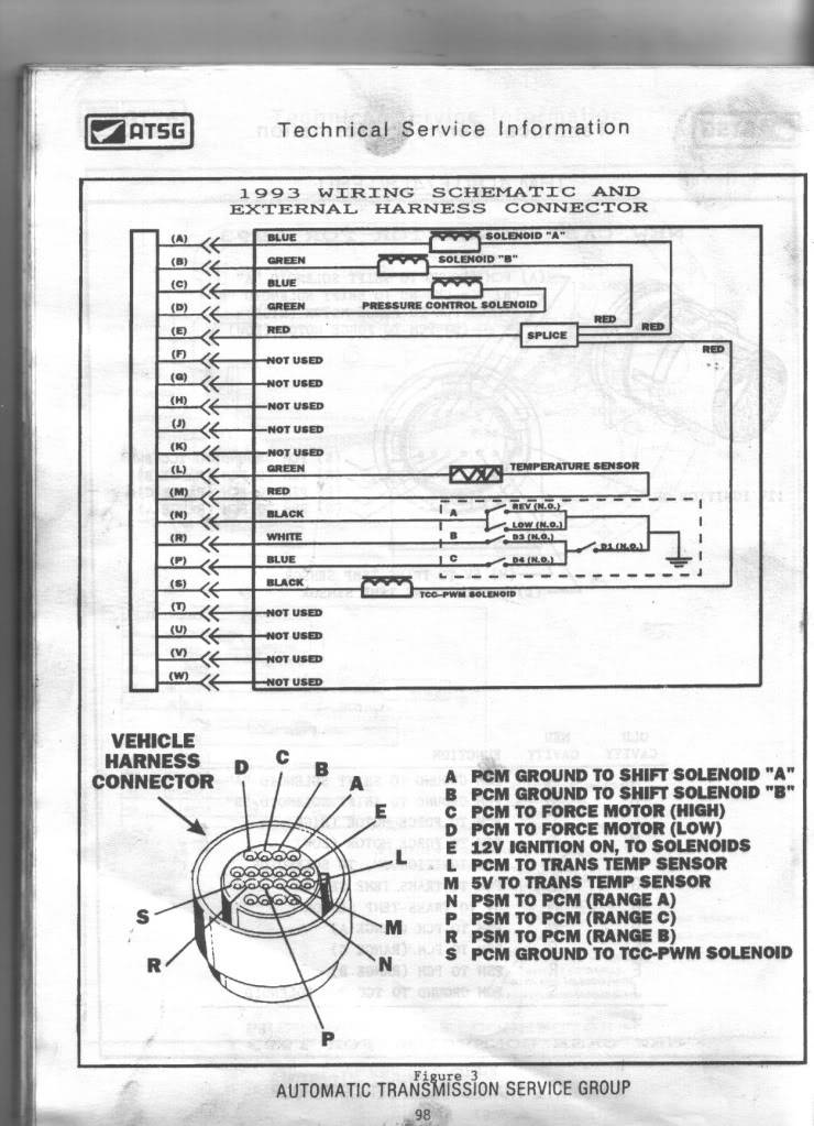
4L80E torque lockup problem Page 2